- 您现在的位置:买卖IC网 > Sheet目录337 > LT3478IFE#PBF (Linear Technology)IC LED DRVR HP CONS CURR 16TSSOP
LT3478/LT3478-1
APPLICATIO S I FOR ATIO
CTRL2 to achieve the desired CTRL2 curve vs temperature.
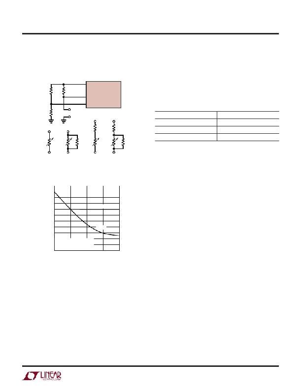
The current derating curve shown in Figure 6 uses the
resistor network shown in option C of Figure 7.
to obtain a resistor’s exact values over temperature from
the manufacturer. Hand calculations of CTRL2 voltage
can then be performed at each given temperature and the
resulting CTRL2 curve plotted versus temperature. Several
10
V REF
iterations of resistor value calculations may be required
R2
R4
13
12
LT3478/LT3478-1
CTRL2
CTRL1
to achieve the desired breakpoint and slope of the LED
current derating curve.
Table 5. NTC Resistor Manufacturers/Distributors
R1
R3
OPTION A TO D
MANUFACTURER
Murata Electronics North America
www.murata.com
R Y
R Y
TDK Corporation
Digi-key
www.tdk.com
www.digikey.com
R NTC
R NTC
R X R NTC
R NTC
R X
If calculation of CTRL2 voltage at various temperatures
A
B
C
D
3478 F07
gives a downward slope that is too strong, alternative
Figure 7. Programming LED Current Derating Curve
vs Temperature (R NTC Located on LEDs PCB)
1100
1000
900
resistor networks can be chosen (B, C, D in Figure 7)
which use temperature independent resistance to reduce
the effects of the NTC resistor over temperature.
Murata Electronics provides a selection of NTC resistors
with complete data over a wide range of temperatures. In
800
700
600
CTRL1
addition, a software tool is available which allows the user
to select from different resistor networks and NTC resistor
values and then simulate the exact output voltage curve
CTRL2
LED CURRENT = MINIMUM
500
400
300
200
100 OF CTRL1, CTRL2
R3 = OPTION C
0
0 25 50 75
T A AMBIENT TEMPERATURE ( ° C)
100
(CTRL2 behavior) over temperature. Referred to as the
‘Murata Chip NTC Thermistor Output Voltage Simulator’,
users can log onto www.murata.com/designlib and down-
load the software followed by instructions for creating an
output voltage V OUT (CTRL2) from a speci?ed V CC supply
(V REF ). At any time during selection of circuit parameters
3478 F08
Figure 8. CTRL1, 2 Programmed Voltages vs Temperature
Table 5 shows a list of manufacturers/distributors of NTC
resistors. There are several other manufacturers available
and the chosen supplier should be contacted for more
detailed information. To use an NTC resistor to indicate
LED temperature it is only effective if the resistor is con-
nected as close as possible to the LED(s). LED derating
curves shown by manufacturers are listed for ambient
temperature. The NTC resistor should be submitted to
the same ambient temperature as the LED(s). Since the
temperature dependency of an NTC resistor can be non-
linear over a wide range of temperatures it is important
the user can access data on the chosen NTC resistor by
clicking on a link to the Murata catalog.
The following example uses hand calculations to derive
the resistor values required for CTRL1 and CTRL2 pin
voltages to achieve a given LED current derating curve.
The resistor values obtained using the Murata simulation
tool are also provided and were used to create the derating
curve shown in Figure 6. The simulation tool illustrates
the non-linear nature of the NTC resistor temperature
coef?cient at temperatures exceeding 50°C ambient. In
addition, the resistor divider technique using an NTC
resistor to derive CTRL2 voltage inherently has a ?atten-
ing characteristic (reduced downward slope) at higher
temperatures. To avoid LED current exceeding a maximum
34781f
13
发布紧急采购,3分钟左右您将得到回复。
相关PDF资料
LT3486EFE#PBF
IC LED DRVR WHITE BCKLGT 16TSSOP
LT3491EDC#TRMPBF
IC LED DRIVER WHITE BCKLGT 6-DFN
LT3492IFE#TRPBF
IC LED DVR HP CONST CURR 28TSSOP
LT3496IUFD#PBF
IC LED DRVR WHT/RGB BCKLT 28-QFN
LT3497EDDB#TRMPBF
IC LED DRIVR WHITE BCKLGT 10-DFN
LT3498EDDB#TRPBF
IC LED DRVR WT/OLED BCKLGT 12DFN
LT3517HUF#PBF
IC LED DRIVER AUTOMOTIVE 16-QFN
LT3519EMS-2#PBF
IC LED DRVR HP CONST CURR 16MSOP
相关代理商/技术参数
LT3478IFE#TRPBF
功能描述:IC LED DRVR HP CONS CURR 16TSSOP RoHS:是 类别:集成电路 (IC) >> PMIC - LED 驱动器 系列:- 标准包装:6,000 系列:- 恒定电流:- 恒定电压:- 拓扑:开路漏极,PWM 输出数:4 内部驱动器:是 类型 - 主要:LED 闪烁器 类型 - 次要:- 频率:400kHz 电源电压:2.3 V ~ 5.5 V 输出电压:- 安装类型:表面贴装 封装/外壳:8-VFDFN 裸露焊盘 供应商设备封装:8-HVSON 包装:带卷 (TR) 工作温度:-40°C ~ 85°C 其它名称:935286881118PCA9553TK/02-TPCA9553TK/02-T-ND
LT3478IFE-1
制造商:LINER 制造商全称:Linear Technology 功能描述:4.5A Monolithic LED Drivers with True Color PWM Dimming
LT3478IFE-1#PBF
功能描述:IC LED DRVR HP CONS CURR 16TSSOP RoHS:是 类别:集成电路 (IC) >> PMIC - LED 驱动器 系列:- 标准包装:6,000 系列:- 恒定电流:- 恒定电压:- 拓扑:开路漏极,PWM 输出数:4 内部驱动器:是 类型 - 主要:LED 闪烁器 类型 - 次要:- 频率:400kHz 电源电压:2.3 V ~ 5.5 V 输出电压:- 安装类型:表面贴装 封装/外壳:8-VFDFN 裸露焊盘 供应商设备封装:8-HVSON 包装:带卷 (TR) 工作温度:-40°C ~ 85°C 其它名称:935286881118PCA9553TK/02-TPCA9553TK/02-T-ND
LT3478IFE-1#TRPBF
功能描述:IC LED DRVR HP CONS CURR 16TSSOP RoHS:是 类别:集成电路 (IC) >> PMIC - LED 驱动器 系列:- 标准包装:6,000 系列:- 恒定电流:- 恒定电压:- 拓扑:开路漏极,PWM 输出数:4 内部驱动器:是 类型 - 主要:LED 闪烁器 类型 - 次要:- 频率:400kHz 电源电压:2.3 V ~ 5.5 V 输出电压:- 安装类型:表面贴装 封装/外壳:8-VFDFN 裸露焊盘 供应商设备封装:8-HVSON 包装:带卷 (TR) 工作温度:-40°C ~ 85°C 其它名称:935286881118PCA9553TK/02-TPCA9553TK/02-T-ND
LT3479
制造商:LINER 制造商全称:Linear Technology 功能描述:700mA Low Noise High Current LED Charge Pump
LT3479EDE
制造商:Linear Technology 功能描述:Conv DC-DC Single Step Up 2.5V to 24V 14-Pin DFN EP
LT3479EDE#PBF
功能描述:IC REG BOOST INV ADJ 3A 14DFN RoHS:是 类别:集成电路 (IC) >> PMIC - 稳压器 - DC DC 开关稳压器 系列:- 标准包装:250 系列:- 类型:降压(降压) 输出类型:固定 输出数:1 输出电压:1.2V 输入电压:2.05 V ~ 6 V PWM 型:电压模式 频率 - 开关:2MHz 电流 - 输出:500mA 同步整流器:是 工作温度:-40°C ~ 85°C 安装类型:表面贴装 封装/外壳:6-UFDFN 包装:带卷 (TR) 供应商设备封装:6-SON(1.45x1) 产品目录页面:1032 (CN2011-ZH PDF) 其它名称:296-25628-2
LT3479EDE#PBF
制造商:Linear Technology 功能描述:DC-DC CONVERTER CURRENT MODE 制造商:Linear Technology 功能描述:DC-DC CONVERTER, CURRENT MODE, 3.5MHZ, D
